


- Feasibility study of port type crack injection method using latex elastic storage tube
Eun-Young Kima and Kwang-Ho Shob,*
aDepartment of Architectural Engineering, Creative Engineering College Wonkwang University, Jeollabuk-do, 54538, Korea
bDepartment of Architectural Engineering, Creative Engineering College Wonkwang University, Jeollabuk-do, 54538, Korea
In the construction site, various crack repair methods were used on concrete structures. Especially, the epoxy injection method was used on the economics, however various problems such as difficulty of material injection under the high pressure conditions, lacks of material injection under the low pressure conditions, and materials separation under the high pressure conditions were occurred. Therefore, there were conducted Mock-up Test and actual application using T-Port at on-site, and investigated the effect of injection on the concrete structure. Moreover, the ultrasonic test was also conducted in order to evaluate before and after repair effects. From there results, it was founded that T-port had a good performance for the crack injection compared to traditional method.
Keywords: T-Port, Injection method, Crack, Repair, Ultrasonic, concrete
Concrete provides various benefits such as strong compressive stress, constructability, and economic efficiency; however, it also has the drawback of crack occurrence because of its vulnerability to tensile forces. Concrete structures are susceptible to various types of cracks, including plastic shrinkage cracks, hydration-heat-induced cracks, drying shrinkage cracks, cracks caused by alkali-aggregate reaction, and cracks due to freezing and thawing, depending on the place and environment [1-2]. Cracks occur due to several reasons such as errors in the design stage, defective construction at the construction site, structural defects, durability degradation, damage to exterior, and corrosion of the reinforcing bar [3-5].
Aged finishing materials, accessories, and facilities can be replaced with new ones, but the structural body, which is the frame of a structure, is difficult to repair and cannot be replaced if a problem occurs [6]. Therefore, it is important to increase the service life of the structural body through proper repairs [7-9].
Various methods and materials have been researched and developed to repair cracks, and have been applied to all defect sites. Among the crack repair methods used at sites, the injection method is the most widely used because of its excellent constructability, economic efficiency, and ability to cover from general cracks to leakage areas [10-11]. However, crack repairs are recognized as additional construction caused by defects rather than as measures to increase the service life; this prompts low-cost construction instead of quality assurance. Therefore, cracks are not perfectly repaired and the continuous recurrence of defects is regarded as normal [12].
As such, this research team adopted a latex elastic storage tube to address the problems of the existing injection method and to ensure constructability as well as economic efficiency. In addition, the effects on injection performance improvement and quality assurance were evaluated after the repairs by developing the method (TPS method) of installing a unidirectional plate valve at the injection port to release the air in a crack. These results were obtained by creating artificial cracks under laboratory conditions; thus, it is necessary to conduct experimental analysis on various crack sizes and depths that occur in actual structures [13-14].
Therefore, in this study, a cracked concrete specimen was fabricated and tested for constructability and quality to assess the applicability of the developed TPS method. The developed method was applied to the cracks of actual concrete structures and assessed for the development of an applicable crack injection method.
Table 1 shows the mock experiment design and mixing ratio. First, the mixing ratio of cement : water : fine aggregate : coarse aggregate in the concrete specimen was designed to be 1:0.4:2:1.8 with W/C of 40% and target strength of 24 MPa. The dimensions of the specimen were 240×120×60 mm.
In addition, artificial cracks with a size of 0.2~2.0 mm were created in the top (T), middle (M), and lower part (L) of the specimen. The artificial cracks were induced by installing 0.1 mm PE film when concrete was casted. Ten levels were designed as experimental parameters, including a plain that is free of cracks, and three levels were designed for each crack. Ultrasonic tests were conducted, and the compressive and tensile strengths were measured according to the KS 2405 and 2423 standards.
Table 2 shows the field application plan of this study. The site location was Texas State University in the United States. Construction was planned for lateral (La), longitudinal (Lo), and overhead (O) cracks among the various types of cracks found in various locations such as walls, beams, and columns in the university. As experimental parameters, ten levels were designed, including a plain that is free of cracks, and three levels were designed for each crack (T, M, and L).
The compressive and tensile strengths were measured according to the KS standards, and micro-crack injection was examined using a petrographic microscope and a digital image analyzer for detailed analysis.
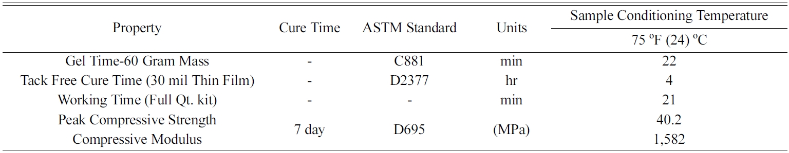
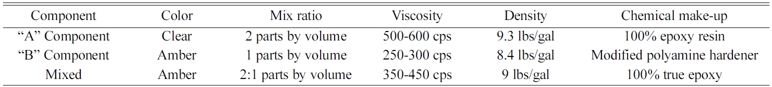
A sealant for application on the crack surface and an injection material were used in this study. Based on the site situation, a sealant and an injection material widely used in the United States were employed. A two-component adhesive was used as the sealant and a two-component low-viscosity epoxy was used as the epoxy. Tables 3 and 4 show their properties.
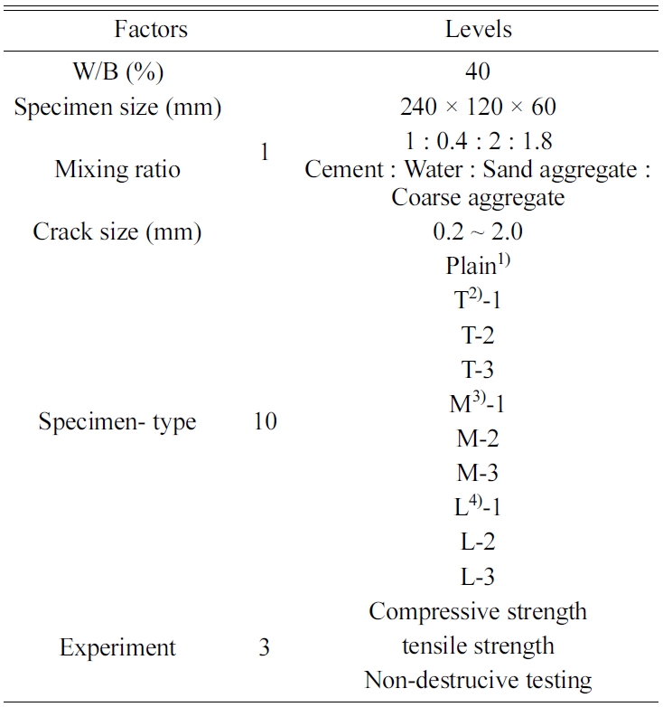
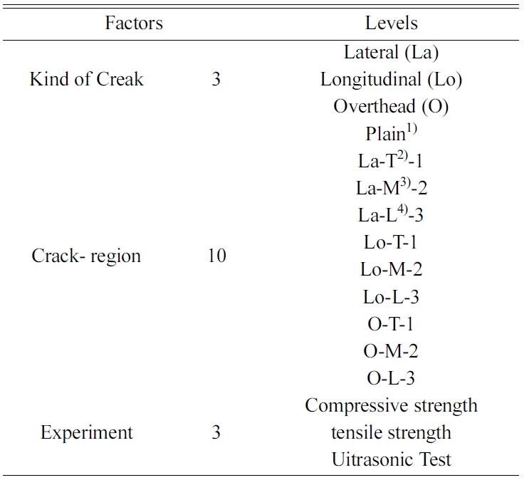
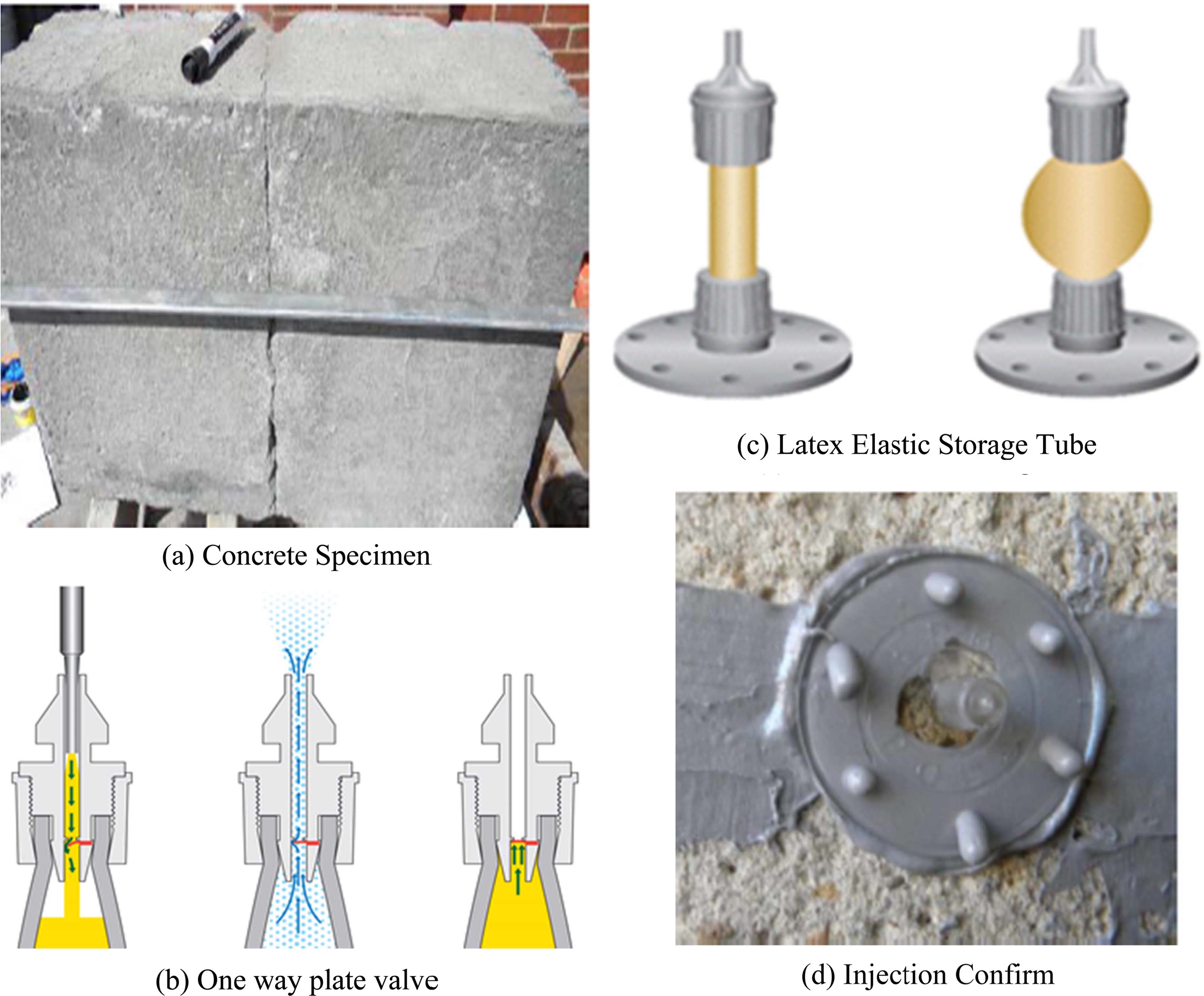
Fig. 1 shows the specimen and port type crack injection equipment used in this study. Artificial cracks with a size of 0.2~2.0 mm were created in the specimen with dimensions of 24×12×6 mm. The artificial cracks were induced by 0.2~2.0 mm PE film when concrete was casted.
The unidirectional plate valve was bent toward the injection direction and opened when the maintenance liquid was injected. Upon completion of injection, the valve was bent in the opposite direction to the injection direction, which automatically closed the injection port as the maintenance liquid that filled the elastic tube pushed the elastic plate toward that direction due to the contractive force of the elastic tube. At this instance, since there was space for air to escape through the smart valve, the air in the crack was pushed and discharged in a natural way.
The storage tube used in this study, which is made of a highly elastic latex material, enables injection deep into a crack because the injection pressure increases as injection progresses. It has the shape of an expanded or contracted storage tube and the injection pressure can be recognized. The latex tube had an inner diameter of 4 mm, an outer diameter of 10 mm, and a length of 48 mm.
|
Fig. 1 Concrete specimen and Port type crack Injection equipment |
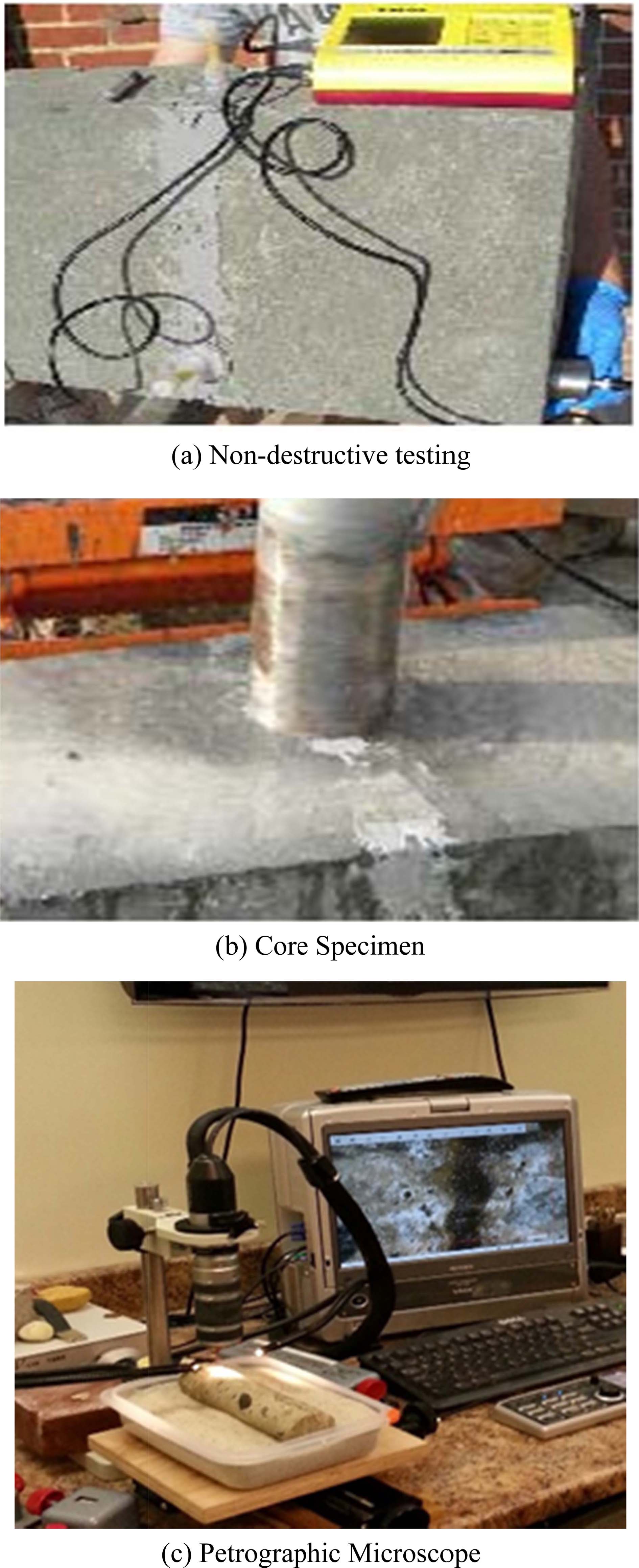
Fig. 2(a) shows ultrasonic testing used in this study. Ultrasonic tests were performed to evaluate the infiltration of maintenance liquid into the concrete in a non-destructive manner. In general, the ultrasonic transit time varies depending on the cracks or pores. The transit time for concrete with completely filled cracks is similar to that for concrete without cracks, while it is delayed for unfilled concrete.
In addition, meters were connected to the two 54-Hz transducers attached to both sides of the specimen using petroleum jelly to be used as a vibrator and a receiver, respectively, and the wavelength transit time through the specimen was recorded.
The compressive and tensile strengths were measured according to the KS 2405 and 2423 standards. The strengths were measured using a UTM-300 Ton device after samples were collected from three positions of the specimen, as shown in Fig. 2(b).
The petrographic microscope used in this study is mainly used for detailed observation and analysis of rocks. Model of petrographic microscope was SMZ-168 BL. Its size was 160 × 160 × 60 mm and the magnification was 20~220 times. Resolution has 1.3M image (1,280 × 1,024) Pixel. As shown in Fig. 2(c), after positioning the core specimens collected from the site on the base plate of the microscope, the filling status of the injection liquid on the concrete surface was observed in detail.
|
Fig. 2 Evaluation methods of Port Type Crack Injection. |
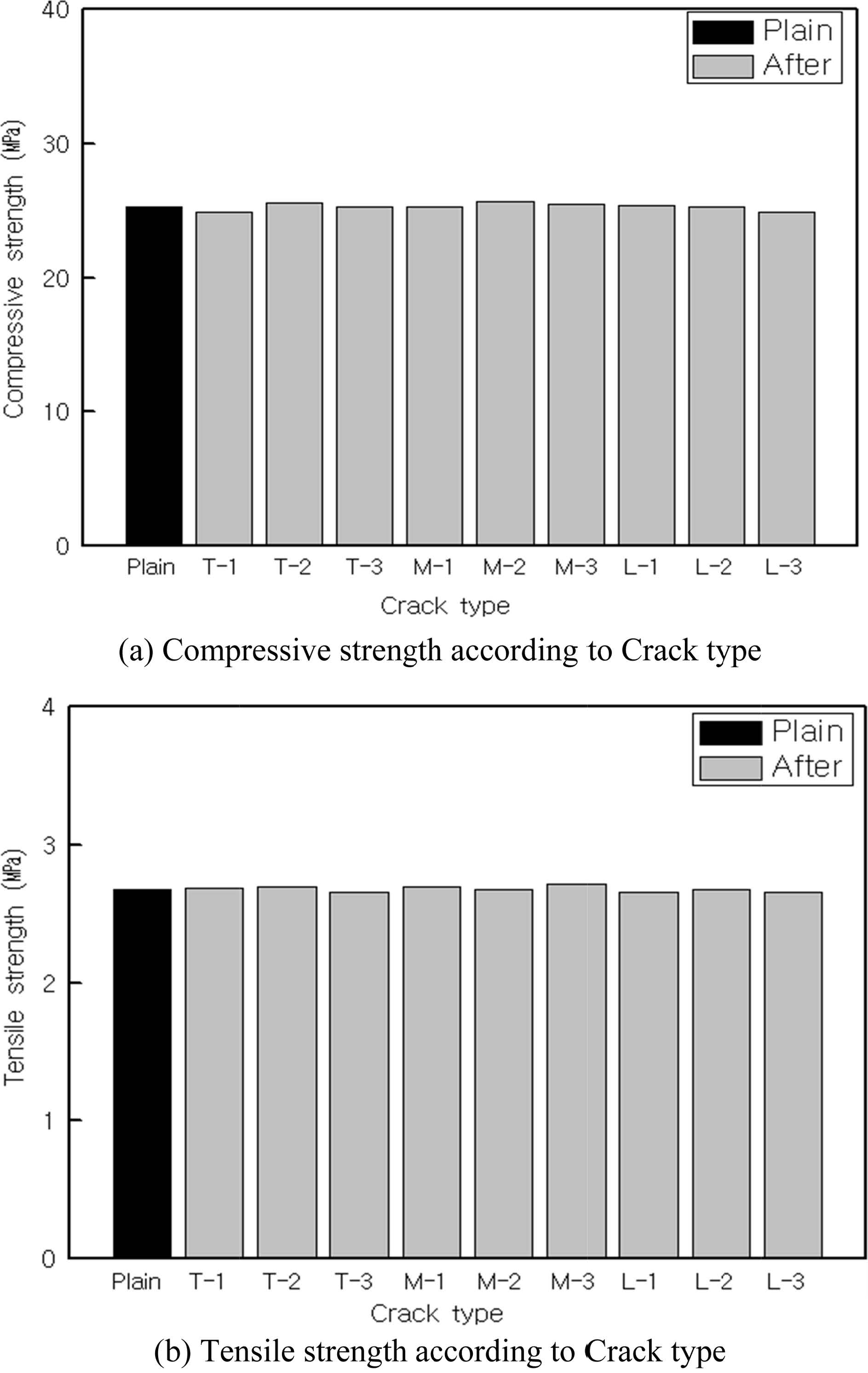
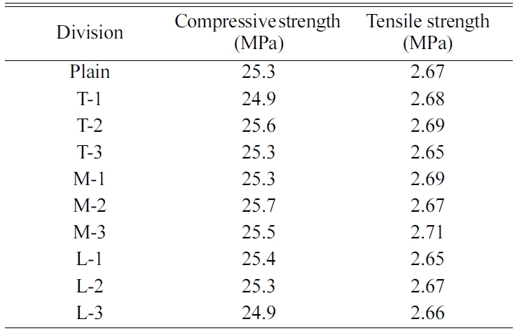
Table 5 shows the measured compressive and tensile strengths according to the crack position, and Fig. 3(a) is shows the compressive strength. The overall compressive strength is similar to that of the plain. In detail, compared to the compressive strength of the plain (25.3 MPa), the compressive strengths of L-1 and L-3 were lower by 1.6% and 0.4%, while those of T-1, T-2, M-2, and M-3 were higher by 0.3, 1.1, 1.5, and 0.7%, respectively. This is possibly because the filling of pores through the 60~80-MPa epoxy injection into the cracks somewhat increased the compressive strength. In addition, T-3, M-1, and L-2 exhibited the same compressive strength as that of the plain.
The tensile strength showed a similar trend as that of the compressive strength, and tended to increase after maintenance. In detail, the tensile strength before maintenance was lower than that of the plain (2.67 MPa). After maintenance, the tensile strength increased by approximately 5% for T-1, 4% for T-2, 4% for T-3, 4% for M-1, 4% for M-2, 3% for M-3, 3% for L-1, 4% for L-2, and 3% for L-3, resulting in an approximately 4% average increase compared to that of the plain. This trend is similar to that of the compressive strength, and is possibly because the complete filling of concrete cracks using the epoxy contributed to the increase in tensile strength.
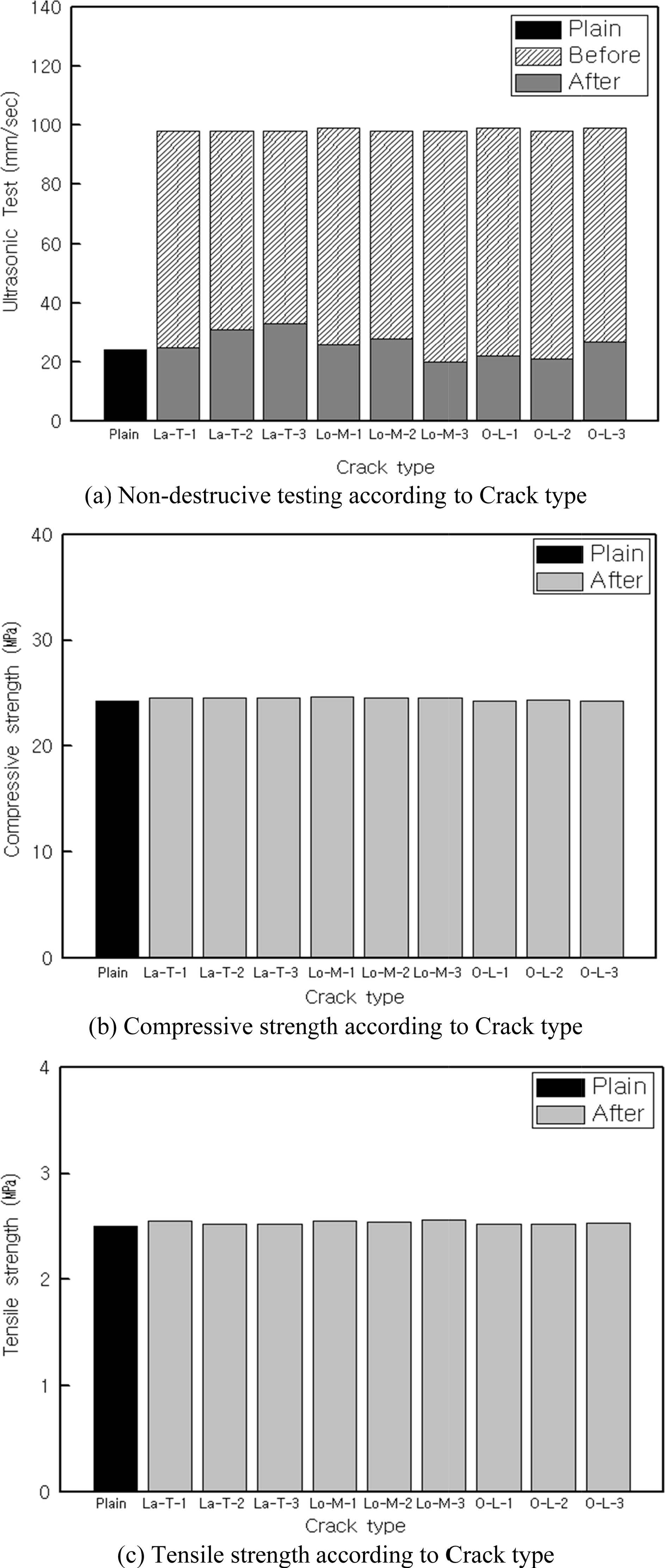
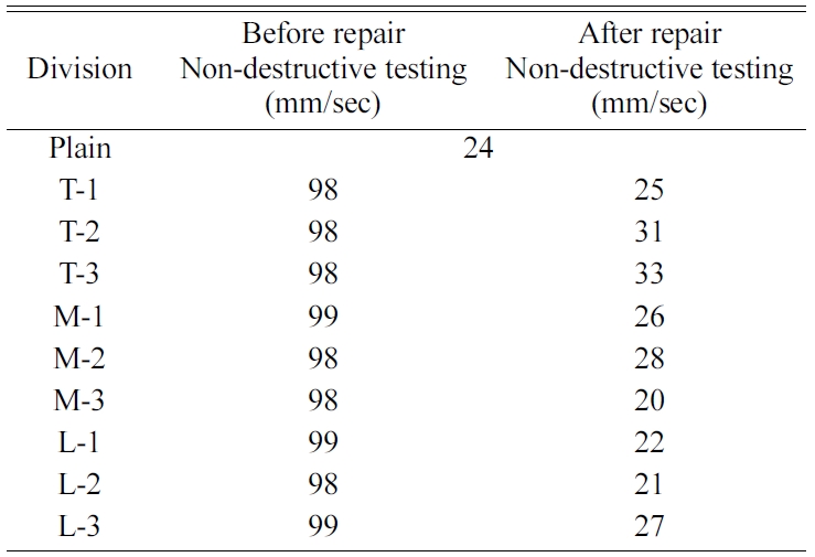
Table 6 shows the results of ultrasonic test according to the crack types, and Fig. 4(a) shows such results on a graph. The ultrasonic waves tended to penetrate at a faster speed after maintenance compared to before maintenance. In detail, the speed increased by 74 mm/s to 98 mm/s on an average compared to 24 mm/s for the plain before maintenance, and the penetration speed for the plain increased by 2 mm/s to 26 mm/s on an average after maintenance. This indicates that the tendency was significantly different before and after maintenance, and is because of the complete filling of the cracks using the epoxy, which confirms the excellent performance of the crack maintenance injection of the TPS method.
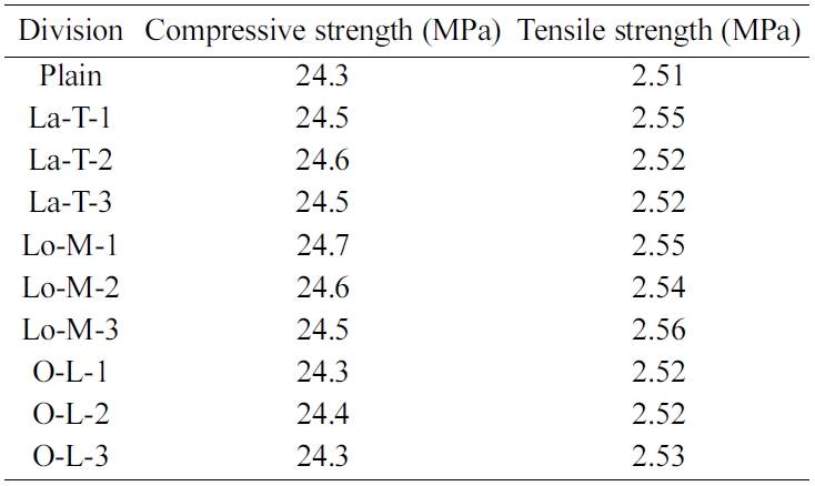
Table 7 shows the measured compressive and tensile strengths according to the crack types, and Fig. 4(b) and 4(c) show such measurements on graphs.
Overall, the compressive strength after maintenance was somewhat higher compared to that of the plain. In detail, compared to the compressive strength of the plain (24.3 MPa), the compressive strength increased by approximately 0.8% for La-T-1, 1.2% for La-T-2, 0.8% for La-T-3, 1.6% for Lo-M-1, 1.2% for Lo-M-2, 0.8% for Lo-M-3, and 0.4% for O-L-2. In particular, the Lo-M-1 combination exhibited the highest compressive strength with 1.6% increase. This appears to be because of the strong adhesion between the epoxy and concrete as well as the high strength of the epoxy, which increased the strength to some extent. In addition, O-L-1 and O-L-3 showed the same compressive strength as that of the plain.
The tensile strength showed a similar tendency as that of the compressive strength, and increased after maintenance. Compared to the tensile strength of the plain (2.51 MPa), the tensile strength increased by approximately 1.5% for La-T-1, 0.4% for La-T-2, 0.4% for La-T-3, 1.5% for Lo-M-1, 1.1% for Lo-M-2, 1.9% for Lo-M-3, 0.4% for O-L-1, 0.4% for O-L-2, and 0.8% for O-L-3. The Lo-M-1 combination, in particular, exhibited the highest tensile strength with 1.9% increase.
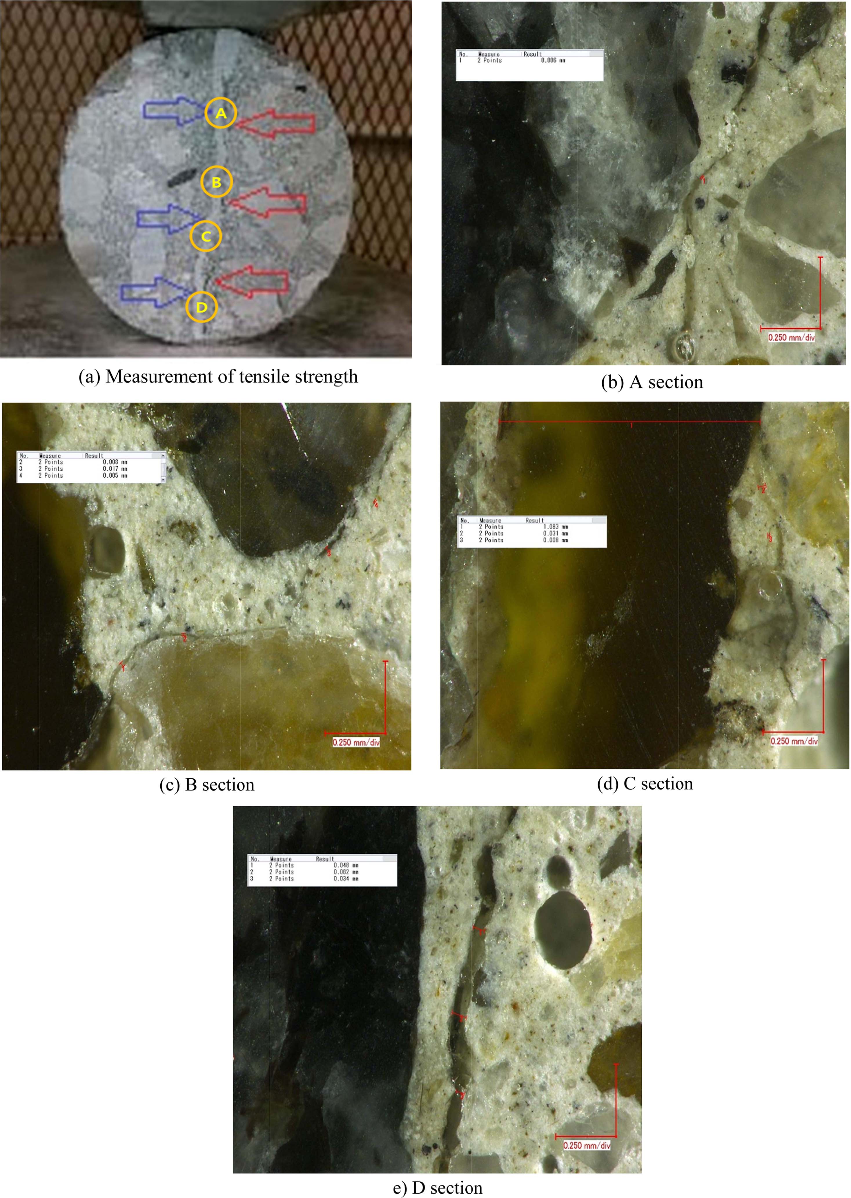
Fig. 5(a) shows the scene of measuring the tensile strength. When pressure was applied to measure the tensile strength of the core specimen, cracks occurred at new positions other than the existing cracks repaired with the epoxy, indicating that crack maintenance was perfectly conducted.
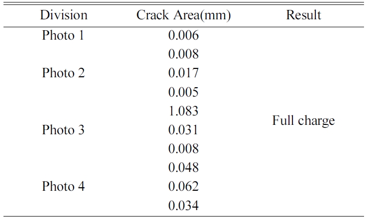
Table 8 shows the results of the micro-crack measurements made using a petrographic microscope and a digital image analyzer, and Fig. 5(b-e) show the scenes of measurement. Overall, it was possible to confirm the complete filling by the maintenance liquid and that the maintenance liquid completely filled the cracks up to 0.01 mm or less.
Table 2 Table 3 Table 4
|
Fig. 3 Evaluation of injection effects on the Mock-up Test Results. |
|
Fig. 4 Evaluation of injection effects on the field test results. |
|
Fig. 5 Photos of injection areas on the surface of specimen. |
In this study, the applicability of the TPS method developed as a crack maintenance injection method was assessed using a mock test and field application experiment. The results are summarized as follows.
1. As observed from the mock test, the compressive and tensile strengths improved after maintenance and were approximately 10% and 4% higher, respectively, on an average compared to those of the plain.
2. In the field application experiment, first, ultrasonic testing revealed that the ultrasonic wave penetrated the specimen at a faster speed after maintenance, resulting in a significantly different penetration rate of approximately 26~98 mm/s on an average.
3. The compressive and tensile strengths significantly improved after maintenance and were approximately 16% and 20% higher, respectively, on an average compared to those of the plain.
4. The examination of micro-crack injection using a petrographic microscope and a digital image analyzer confirmed that the maintenance liquid completely filled the cracks up to 0.01 mm or less.
In summary, the TPS method, which is a port-type crack injection method that employs an elastic storage tube, was assessed to be effective in improving the quality after crack maintenance owing to its excellent constructability and injection performance, and is expected to solve the problems of the existing method and reduce the recurrence rate of defects.
This paper was sponsored by Wonkwang University in 2018.
- 1. S.H. Kim, B.I. Kim S.K. Oh, J. Korea. Recyc. Const. Resou. Inst, sept. 4[3] (2016) 322-329.
- 2. R.H. Geraldo, O.G. Teixeira, S.R.C. Matos, F.G.S. Silva, J.P. Goncalves, G. Camarini, Constr. Build. Mater. Mar. 165[20] (2018) 914-919
- 3. C. A. Issa and P. Debs, Constr. Build. Mater. 21(2007) 157-163.
-

- 4. A. Shash, Constr. Build. Mater. Feb. 19[1](2005) 75-79.
-
- 5. M. Ekenel, and J.J Myers, Constr. Build. Mater. 21 (2007) 1182-1190.
-
- 6. S.Y Kim, B.I. Kim, S.G. Oh, Proc. Kor. Concr. Inst. 30[2] (2018) 705-706.
- 7. T.H. An, K.M. Kim, KSCE. Mar. 64[3] (2006) 68-71.
- 8. S. Kim, Y.H. Yu, D.K. Park, Proc. Arch. Inst. Kor. May. 12[5] (1996) 249-256.
- 9. H.C. Shin, G.Y. Kim, S.W. Park, Proc. Kor. Concr. Inst. Sept. 16[5] (2004) 44-48.
- 10. S.P Kang, S.J. Hong, Proc. Arch. Inst. Kor. Apr. 25[4] (2009) 161-168.
- 11. J.P. Kim, C.G. Jeon, H. Jeong, H.S. Kim, Proc. Kor. Concr. Inst. 7[3] (2007) 33-39.
- 12. K.M. Kim, J. Ceram. Process. Res. 16 (2015) 144-148.
-
- 13. K.M. Kim, J.K. Sin, Y.J. Pakr, Proc. Kor. Concr. Inst. 17[4] (2017) 41-47.
- 14. K.M. Kim, J.K. Sin, Y.J. Pakr, Proc. Kor. Concr. Inst. 30[1] (2018) 357-358.
 This Article
-
2019; 20(S1): 56-62
Published on Jul 20, 2019
- Received on Dec 9, 2018
- Revised on Jun 25, 2019
- Accepted on Jul 5, 2019
Services
- Abstract
introduction
experiment procedure
results and discussion
conclusion
- Acknowledgements
- References
Shared
Correspondence to
- Kwang-Ho Sho
-
Department of Architectural Engineering, Creative Engineering College Wonkwang University, Jeollabuk-do, 54538, Korea
Tel : +82-63-850-6707
Fax: +82-63-843-0782 - E-mail: wk2000@nate.com
Clean-Energy Research Institute(CRI), Hanyang University, 222, Wangsimni-ro, Seongdong-gu, Seoul, 04763, Korea
Tel: +82-2-2220-0509 E-mail: jcpr@hanyang.ac.kr